Published by Nig on 27 Oct 2013 at 08:25 pm
Micom-Borer 2400L
Micom-Borer 2400L
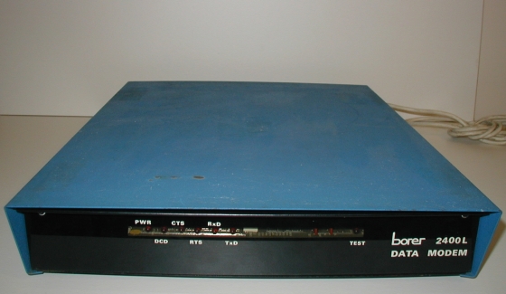
The first of a couple of posts featuring modems that used to reside on the home-made shelving ‘rack’ in the Comms Room. A monstrous unit, with a metal case so rather on the heavy side, and whose size defies its dimunitive 2400bps data speed. This would have been used to provide access to the mainframe via the 7171 controller for remote sites. At the other end of this would have been either an IBM or Memorex CRT VDU. Green-screen, natch.
Looking at the front of this, we see a dark front cover, behind which are a series of LEDs to indicate the state of the carrier, the RTS/CTS signals and the TX and RX of data. There is also a test LED, which would indicate that the unit was in test mode. This was set by a toggling a dip-switch that is revealed when the front cover is removed.
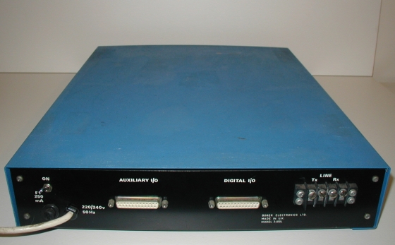
At the back, we see two V24 D-sub connectors, one for the digital I/O, and one Auxilary. This latter could have been used for a printer, I presume, but I don’t recall us ever running remote printing via these modems. Printing, if any, would have been to a printer connected directly to the VDU. In addition, there is a screw terminal for connecting the to the BT line. If we were lucky, someone (and I’m looking at you Adrian) would have actually put terminating lugs on the end of the end cable, but usually the ends of the cable were just wrapped (or not) around the posts before the screw was tightened.
The modem at the Comms Room end would have its serial port connected directly to the IBM 7171 controller and the remote modem would have the VDU connected to its corresponding serial interface. If you think that this was just one of about 20 or 30 modems ‘installed’ on the racking, then you may be able to imagine the mess that resided at the back of the old rack, with each modem having its mains, serial and line cables coming out the back and trailling off to who knows where!
Incidentally, I have a pair of these monsters, both of which still function.