Published by Nig on 27 Oct 2013
Borer Data Line Driver
Borer Data Line Driver
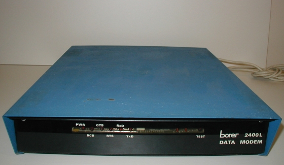
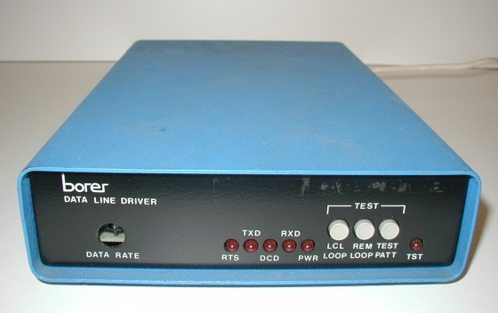
The second of the modems from the original Comms Room installation and a marked improvement on the previous Borer modem. This still features a metal case, but is probably about a third of the size of the 2400L discussed previously. One significant improvement, apart from the size, is that this modem could be run at various data rates, ranging from 600bps to a whopping 19200bps.
Again, this would have provided remote access to the IBM 7171 controller.
Like the previous Borer modem, this device had the same light blue cover and a black front, tho’ in this case, it is not easily removeable. A similar array of LEDs adorn the front, with indicators for DCD, RTS and both TX and RX. In addition, buttons are provided in order to apply loopback tests on the line, either local or remote and these also contributed to common issues in that old environment, where test buttons were accidentally latched when other work was being carried out on another piece of kit. Still, these were an easy fix;-) One further adornment is a thumbwheel accessible from a hole in the front, which was used to set the device’s data rate.
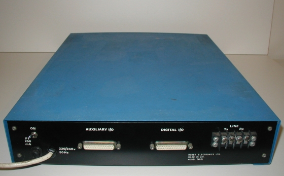
Around the back, along with the line terminator and serial connector, is a nice little table which shows the data rates available with this device. This also shows that this could run either asynchronously (presumably taking the line speed from the speed of the data on the serial interface) or synchronously. One hint as to the actual speed that this device provided to the end user is that the thumbwheel on the front, is set to position 4 which corresponds to 4800 Synch on the table. As I do not recall ever changing this in all the years this has been in the loft, and both modems I have are set the same, it is safe to presume that this did, indeed, run at 4800bps. What lucky folks those users were;-)
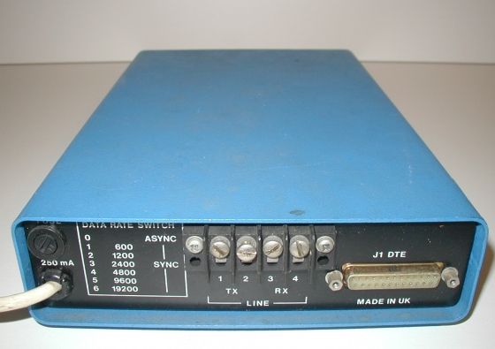
Again we see that the line termination was done using screw-terminals. It wasn’t until theses devices were replaced that we started using RJ11 cables to connect modems to BT lines, although some BT lines were actually presented this way, the modem technology lagged a little way behind.
As with the previous Borer modem, I possess a working pair of these and the glowing LEDs of one them appear in the header graphic on the site:-)